51 Connecting Switches or push button. The bellow wiring diagrams require setting the inputs to use pull-down resistor.

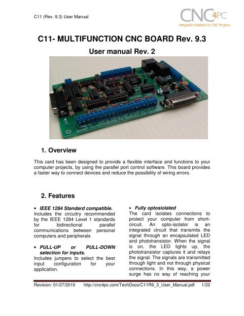
C11 Multifunction Cnc Board Rev 9 3 Stepper Motor
The manual says the 5V should come from the PC.

C11 breakout board wiring diagram. R value to Connect PNP open collector proximity sensor with the C11. Output voltages from the PCB are. If anyone has an CNC4PC C11 breakout board to Xylotec wiring diagram that would be a bonus.
It powers the breakout board. The smaller leads feed 74V AC to the board in 2 places. Please use a 300 HZ PWM base frequency with the PMDX-107.
81 Connecting Switches or push button. Isolate the PC Motherboard from electrical problems that would otherwise fry the Motherboard. PMDX-126 The PMDX-126 is an isolated breakout board with support for 9 inputs 16 outputs and an interface for controlling a VFD using the optional PMDX-107 NOTE.
Wiring diagram to connect switches 82 Connecting NPN sensors. The wiring of the parallel breakout board from the output terminals to the driver digital pulse step pulse and direction lines are explained. Products for CNC and motion control applications since 1998.
In addition many refer to USB Motion Controllers such as the. ESS and C11G help needed. You will hear a click and the Garmin 660 is held firmly in place.
The bellow wiring diagrams require setting the inputs to use pull-down resistor. June 15 2018 033457 AM. 1 C10 Bidirectional Breakout Board 2804 or C11 - 129 Total 68674 to 79675 New.
Keep in mind noise can be transmitted into output signals that. Of the input pulses. Hi I think there might be two ways you can do this.
Wiring Sample C11GS Rev2 with Huanyang Size. The toroidal PS has several outputs. 17018 KB Wiring Sample C11G with VFD Huanyang Size.
Use this kit to hard wire the Aera 660 into an aircraft. 05-28-2007 1248 PM 2. Design manufacturing and support based in the USA.
These are both very important functions. Variety of 36 volt club car golf cart wiring diagram. Garmin AERA 660 Pdf User Manuals.
16578 KB Wiring Sample C11G Rev87 with Speed Control for KB-120 Size. It looks like the shaft is stuck or something. 1963 Chevy 2 Wiring Diagram.
8 User Manual. The largest leads feed 90V to the bridge rectifier which passes 90V DC to the capacitor board. The new parallel breakout board appears a bit different but the process of wiring and testing is the same.
View Profile View Forum Posts Community Moderator Join Date Mar 2003 Posts 35506. First as tweakie has suggested use the capabilities of your C11 breakout board. Simply put the CNC Breakout Board has two functions.
66666 KB Wiring Sample C11G Rev87 with Speed Control for Minarik Size. The below wiring diagrams are an example any input can be used for the connections. C11 Breakout Board Wiring Diagram.
72VDC to the BOB then to the motor controller. However while i was messing in the motor tuning tab one motor suddently stopped. This guide even consists of recommendations for additional materials that you could need in order to complete your assignments.
Ducati Monster 696 Wiring Diagram. C11 breakout board kl-5056 digital drivers nema2 570oz motors 48v power supply 5v power supply. I followed the wiring diagram provided by Arturo and now it works.
7 Wiring diagram to connect switches. My reading of the manual suggests that its analogue output is related to the frequency. These grounds must be common with the grounds of the speed control connection but must be kept isolated from the grounds of the board.
MX3660 3-axis Digital All-in-one Drive - This new driver is like the Gecko g540 with an integrated break out board but is digital with 60vdc 6 amps 5 inputs 4 outputs and spindle control. Reply 2 on. Go to the new parallel breakout board to get more information and the wiring diagram.
72VDC to the BOB. This card must be powered while your system is under power. Incorrectly wiring the power cable with bare wire leads can result in.
70918 KB Wiring Sample for Limit PNP to Breakout Board Size. Smart Sensors for Industrial Applications Krzysztof Iniewski 2017-12-19 Sensor technologies are a rapidly growing area of interest in science and product design embracing developments in electronics photonics. Id check with Arturo to see if you can use another source safely.
4 Wiring diagram to connect NPN open collector proximity sensors. The below wiring diagrams are examples any input can be used for the connections. Translate the signals used to run a CNC machine to and from the signals a PC expects.
Switches using different voltages can be connected using the diagrams that follow. Will work with any of the motors I recommend here. Wiring diagram to connect NPN open collector proximity sensors.
Melex Electric Golf Cart 6 Volt Wiring Diagram. It is recommended that. The pins wiring was wrong.
View entire document on a single page. 8 Wiring diagram to do an Auto Tool Zero C11 Rev.

Cnc Wiring Diagram Recherche Google Diy Cnc Cnc Machine Projects Cnc

Complete Wiring Diagram Cnc 6 Axis Interface Breakout Board With Relay And Spindle Control Breakout Board Cnc Mach3
0 komentar